Is your team still designing software architecture diagrams manually? Spending a lot of time updating the diagram or finding it hard to collaborate?
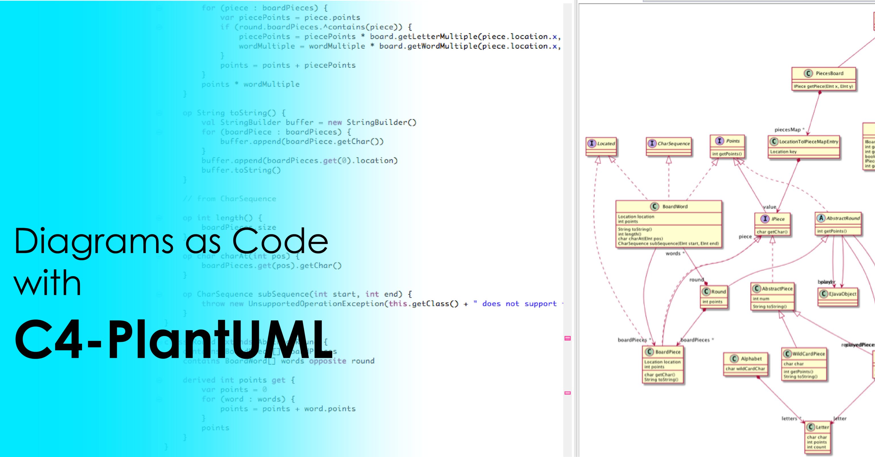
Take a look at the C4-PlantUML, which allows you to generate consistent and up-to-date diagrams directly from your source code. PlantUML is a popular diagramming tool that comes with the support of the C4 model, a standardized method to visualize software architecture, making it an unavoidable tool to create clear, easily maintainable, and easy-to-understand diagrams for your software development project.
In this article, we’ll briefly discuss the C4-PlantUML and explore its key benefits. We’ll also dive into common PlantUML diagrams.
What is C4-PlantUML?
If you’re a very beginner in the world of software architecture, let me introduce you to the game-changing tool: C4-PlantUML.
PlantUML is a powerful open-source tool that lets you generate an architectural diagram quickly and efficiently from plain text descriptions, eliminating the use of manual design tools. It’s an effective way to visualize software architecture, making it easier to understand and communicate complex systems. When combining PlantUML with the C4 software architecture model, they generate software architecture diagrams that are communicative, easy to understand, and version control friendly.
Why to Use C4-PlantUML?
The C4-PlantUML significantly enhances the consistency, clarity, and maintainability of the software architecture documentation. But that’s just the beginning, there are several key reasons to use C4-PlantUML for diagramming. Let’s explore them.
Standardized Visualization with the C4 Model
The C4 Model comes with a standardized way to visualize software architecture at different levels of detail. These are context, container, component, and code. This hierarchy enables effortless communication with complex systems for different levels of audiences, from stakeholders to developers. The C4-PlantUML leverages the C4 model, ensuring that your diagram is consistent and aligned with the best practices in software architecture documentation.
Code-Driven Diagrams
The C4-PlantUML lets you generate diagrams directly from code, eliminating drawing diagrams manually using mostly the drag-and-drop interface. This approach reduces the time and effort required to create and update diagrams.
Version Control
The C4-PlantUML supports you with code-based diagram designing. Since the diagrams are code-based, you can easily be integrated into your version-control system for further review and update by the collaboration of team members. This ensures that the documentation remains accurate, up-to-date, and aligned with your latest codebase.
Flexibility
The C4-PlantUML provides you the flexibility to accommodate diagram customizations and extensions through a structured approach to diagramming. This flexibility allows you to create, modify, and update diagrams effortlessly without losing consistency or clarity.
Consistency Across Projects
Using C4-PlantUML in multiple projects ensures a consistent approach to documentation, making it easier to understand and compare different systems within your organization. This consistency is helpful for large companies where multiple teams work together and your project requires cross-team collaboration.
5 Common PlantUML diagrams
PlantUML allows you to create a wide range of software architecture diagrams where each comes with a unique purpose throughout the entire development process. Let’s dive into some of the most common ones,
Sequence Diagrams
Sequence diagrams are effective when describing the interactions between objects over time. This diagram represents the real-time data flow and the order of operations within a system. Sequence diagrams are often used to model the dynamic behavior of the system.
Class Diagram
Class diagrams offer a static view of your system, showcasing classes, attributes, methods, and relationships. They’re essential for modeling the structure of your code. By representing the system classes and their interactions, class diagrams help in planning and understanding the architecture of an application. They also serve as a reference for developers during implementation, ensuring that the design is correctly translated into code.
Activity Diagram
The activity diagram demonstrates the flow of control, or data within the system, including branching, parallel execution, and synchronization. It represents the steps involved in a workflow or process. Activity diagrams are ideal for modeling complex system operations and business processes.
Use case Diagrams
The use case diagrams allow you to describe the functional requirements of the system, representing how the user interacts with the system. There are two main components of this diagram: actor and use cases. The actors are the users or other systems and the use cases are the functionality of the system. The use case diagram helps you to capture the high-level functionality of the system and identify the roles that interact with it.
Component Diagrams
Component diagrams are vital when you’re dealing with complex system architecture. It shows the organization and dependencies among system components. Component diagrams help to visualize the modular structure of the system mostly used for microservices or component-based system architectures.
Wrapping Up
Maintaining clear and up-to-date documentation is crucial in the fast-paced world of software development. The C4-PlantUML transforms the traditionally static and manual process of diagramming, offering a dynamic and code-driven approach.
Advanced diagramming tools like Inno.navi allow you to craft software architecture diagrams automatically in just a few minutes by simply dragging and dropping the code base.
If you have any questions or require further assistance, feel free to contact us and let us help you.
Excellent post. Keep writing such kind of info on your page.
Im really impressed by your blog.
Hello there, You’ve done a fantastic job. I will definitely digg it and personally recommend
to my friends. I’m confident they will be benefited from this website.